
Detection of Cracks Using Image Processing
img { max-width: 50%; height: auto; display: block; /* Added for center alignment / margin: 0 auto; / Added for center alignment */ }
In the next several decades, the US needs to fix existing infrastructure, nearly all of which is concrete. According to the American Society of Civil Engineers, the amount of money needed is estimated to be roughly $6 trillion. To prioritize and plan for the repair operations of concrete infrastructure, we need to inspect and monitor concrete structures on a regular basis. Since a manual inspection is time-consuming, labor-intensive, and dangerous for workers, the mobile-robotics and machine-learning research communities have been making significant efforts to automate the inspection process.
Autonomous drones can take pictures of buildings and location of suspect crack sites. These images can be processed to highlight the development of cracks. My project uses clever image processing techniques such as dilution, erosion and contour tracing to detect cracks from images.
The process of detecting cracks in an image involves several steps, employing various image processing techniques. One of the key techniques used is thresholding. Thresholding helps segment the image into regions of interest, which in this context means highlighting possible crack areas.
Gray Scale Conversion: The RGB image is first converted to grayscale. This simplification is done to make the subsequent processing steps computationally efficient and to ensure that the focus is on the intensity variations in the image, which are crucial for crack detection.
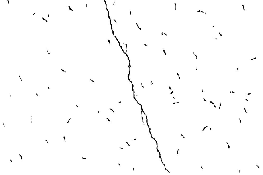
Binary Thresholding: The grayscale image undergoes binary thresholding with a set threshold value of 128. This means any pixel value above 128 will be set to 255 (white) and below will be set to 0 (black). The threshold value is chosen based on the assumption that cracks will typically be darker than the surrounding material. Therefore, this thresholding step will convert potential crack regions to black, while the rest of the image turns white.
Erosion and Dilation: Morphological operations, specifically erosion followed by dilation, are applied to the binary image. The erosion operation uses a cross-shaped structuring element and shrinks the black areas, which helps in eliminating noise and narrowing the width of the cracks. The subsequent dilation operation slightly expands the black areas, restoring the width of the cracks to a more accurate representation. This step assists in making the crack regions more distinct and continuous.
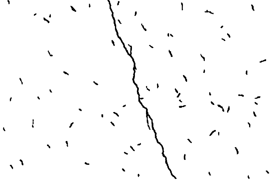
- Contour Tracing: Contours in the image are traced, effectively outlining the boundaries of all black regions. This helps in identifying distinct blobs or regions that might correspond to cracks.
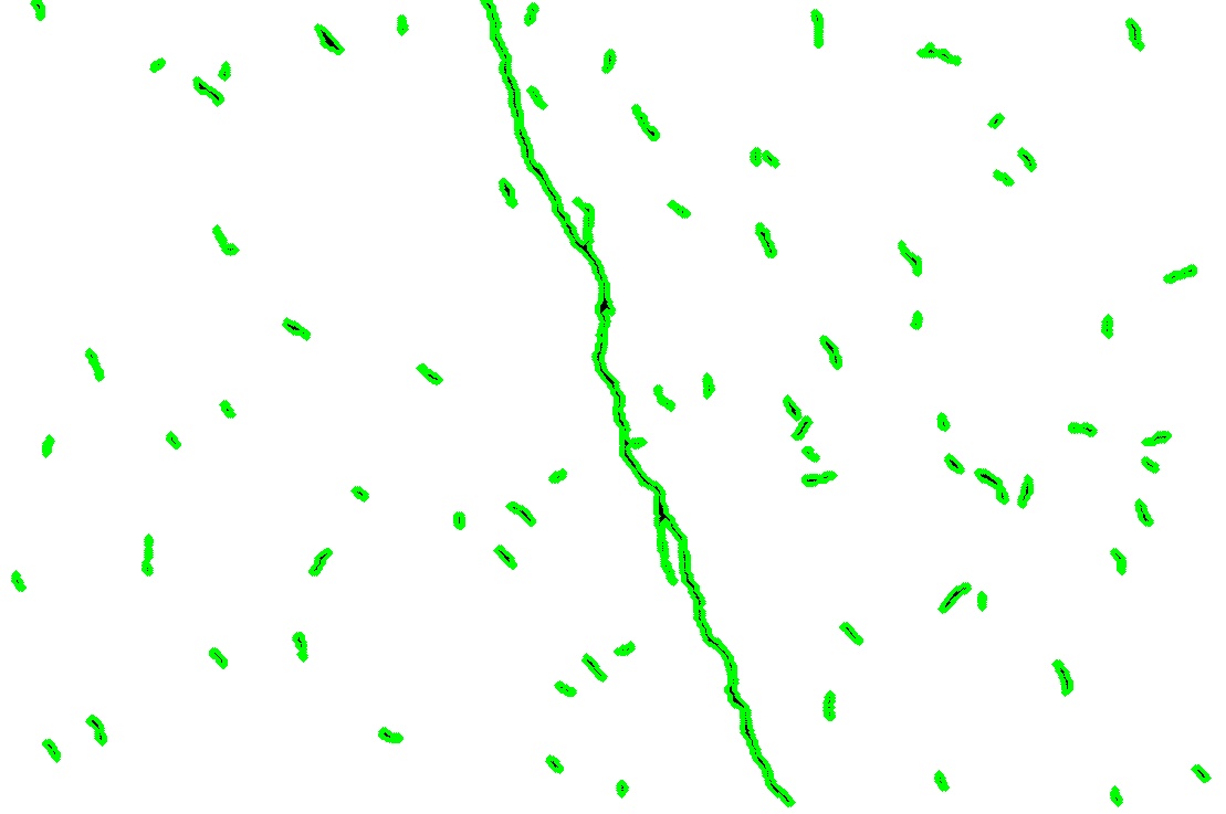
Roundness Calculation and Filtering: For each detected contour, a roundness measure is calculated using the formula: Roundness=4×�×AreaPerimeter2Roundness=Perimeter24×π×Area Where Area is the area of the contour and Perimeter is its perimeter. A genuine crack will typically have a lower roundness value due to its irregular shape, unlike a circular or oval blob. The contours with roundness values below 0.1 are considered as potential crack regions. This threshold was chosen empirically to filter out regions that don’t exhibit the elongated and irregular shape typical of cracks.
Thinning: The potential crack regions undergo a thinning operation to reduce the cracks to their central axis, making them more pronounced and easier to analyze. The thinning operation iteratively erodes away the pixels on the boundary of the black region until a skeleton representation of the crack is left.
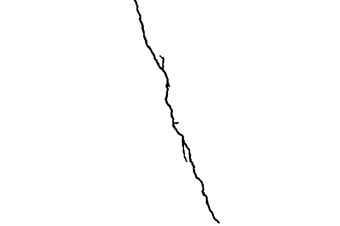
By following this process, the algorithm effectively highlights regions in the image that have a high likelihood of being cracks. However, it’s worth noting that the chosen thresholds and parameters might need to be adjusted depending on the specific characteristics of different datasets or image conditions.